
Postion: Home > Our Case > Stamping & Bending >

 CATEGORIES
Good bending design starts before the press brake is set up. Material, temper, thickness, bend radius, flange length, hole position and cosmetic requirements all affect the manufacturing route.
Hongming Sheng reviews customer drawings for custom brackets, panels, covers, enclosures and welded assemblies—from prototypes to repeat production.
Send PDF, DWG/DXF and STEP/STP files directly to:
info@hms1688.com
Leave Contact & Project DetailsThe online form collects contact information and basic project details. Please email drawing attachments separately.
Stainless steel, aluminum, mild steel and galvanized sheet do not bend in the same way. Include the exact grade, temper and sheet thickness.
An inside radius near one material thickness is a common starting point—not a universal rule. Alloy, temper, grain direction, tooling and angle must be reviewed.
Mark important dimensions, datums, bend directions, tolerances, cosmetic faces and any areas that must remain free of tooling marks.
STEP/STP supports geometry review; PDF or DWG/DXF communicates tolerances, threads, finishes and inspection requirements.
The punch forms the sheet into a V-die without fully pressing it to the die bottom. It is flexible and widely used, but angle control depends on springback and machine setup.
The sheet is pressed more closely against the die surfaces. Tool angle, die opening and material response must match the required result.
Higher force plastically sets the bend area. It can improve angular repeatability but requires greater tonnage and is not the preferred route for every part.
Useful for selected panels, edges and flanges. Part size, visible surfaces and the risk of marking should be reviewed.
Creates two opposite bends to form an offset. Offset height, tooling access and deformation near adjacent features require attention.
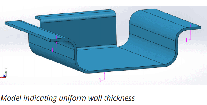
Uniform sheet thickness simplifies tooling selection and bend compensation. If several thicknesses or joined materials are involved, identify them clearly in the assembly drawing.
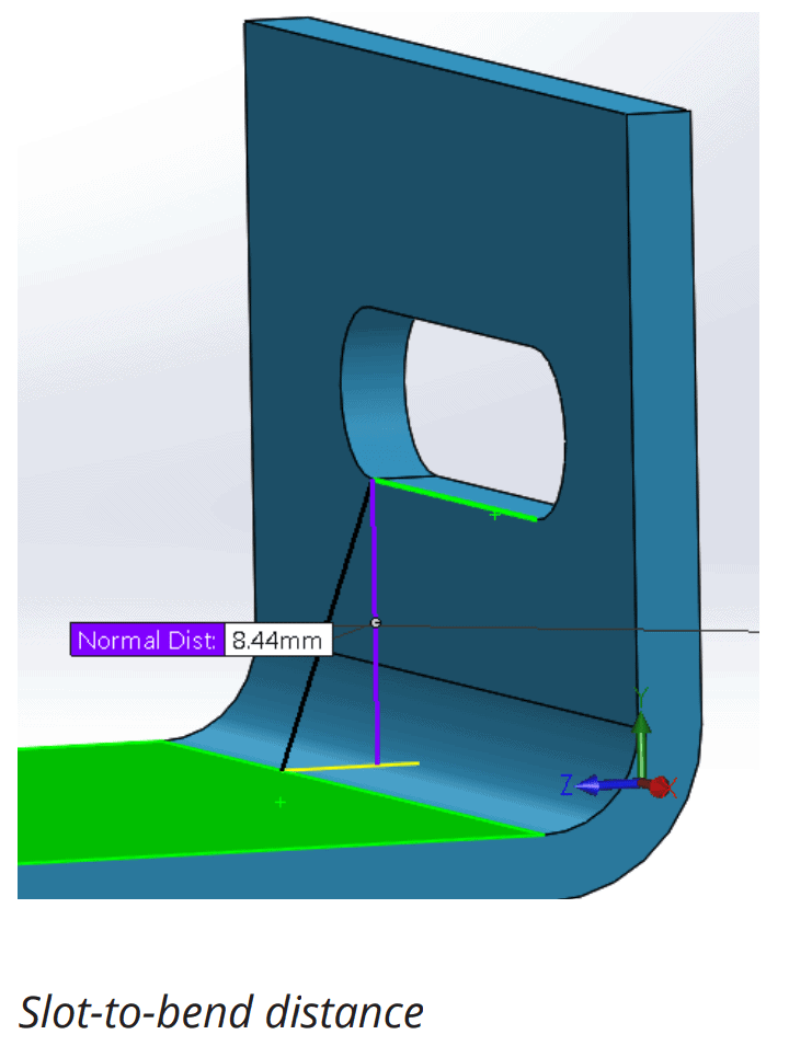
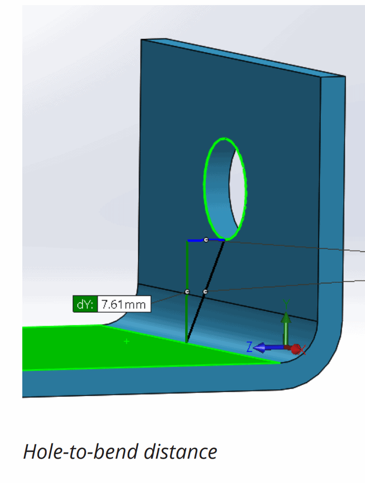
Features too close to a bend may stretch or distort. As an initial DFM guide, allow about 2.5T from a hole and about 4T from a slot; final clearance depends on radius, die opening and geometry.
Using consistent radii can reduce tooling changes and setup time. Avoid unnecessarily small radii, especially in hard aluminum, thick sheet or bends across an unfavorable grain direction.
Curl diameter, opening, straight length and nearby holes need enough clearance for the forming tool. Confirm functional and safety requirements before detailing the edge.

Thin sheet limits countersink depth. Identify the fastener, required seating condition and whether an extruded hole, formed feature or secondary insert is more suitable.
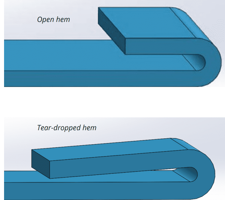
Open, closed and teardrop hems behave differently. Material hardness, return length, inside opening and appearance requirements influence feasibility.
Chamfers and corners must leave enough material and tool access so the flange does not tear, bulge or interfere during bending.
Successive bends can trap the part or collide with the punch, die or machine. Provide sufficient flange access and review the sequence before finalizing the design.
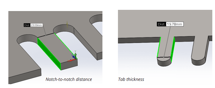
A useful starting point for notch-to-bend clearance is approximately 3T plus the bend radius. Tab spacing should also allow stable cutting and forming.
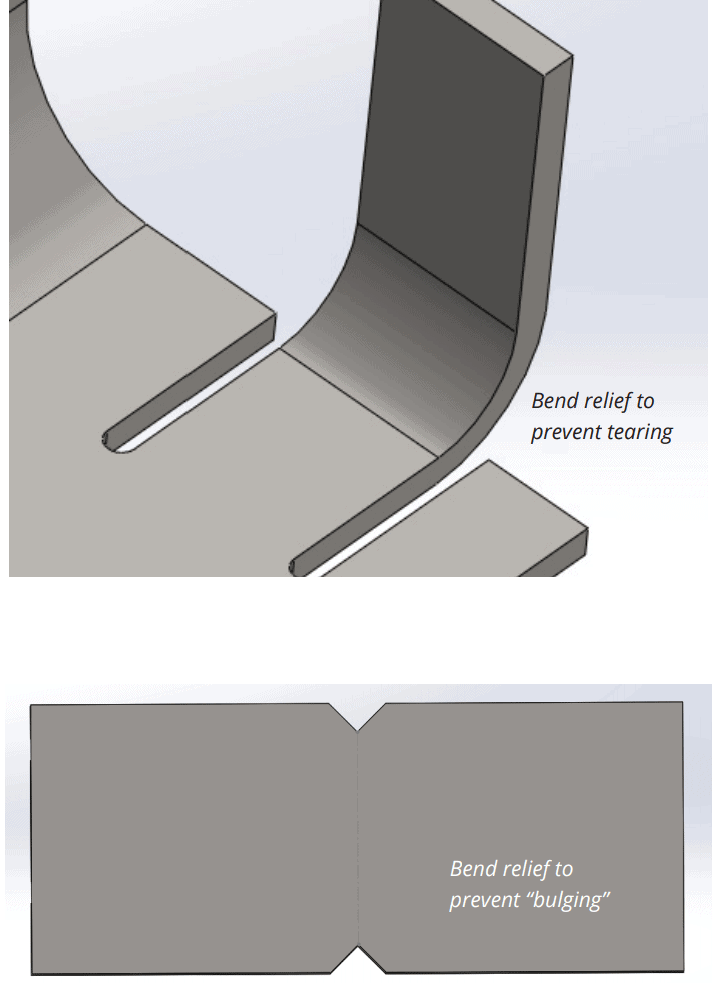
Relief cuts help control tearing and bulging where a bend terminates. Relief width is commonly at least the material thickness, with length extending beyond the bend radius.
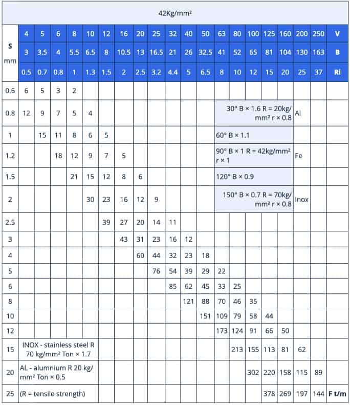
Required press force is influenced by material strength, thickness, bend length, die opening, angle and inside radius. A reference chart is useful for planning, but final tonnage must be confirmed for the actual material and tooling setup.
Related capability: OEM/ODM Sheet Metal Bending Service
Send your drawings and production requirements for bend-radius, tooling-access, tolerance and manufacturing-route review.
Email: info@hms1688.com
Request Bending Project ReviewThe inquiry form does not accept drawing attachments. Please email PDF, DWG/DXF and STEP/STP files directly.
Customer drawings, CAD data and technical information are handled confidentially. NDA support is available for custom projects.

Contact us and just send us your drawing (SolidWorks,ProE,CAD,PDF,DXF...)
Links: Custom Sheet Metal Enclosure Fabrication | Metal Stamping Services | Sheet Metal Fabrication Services | precision cnc machining and milling services | Metal Welding Services | metal Cutting Services | Metal Bending Service | Metal Surface Treatment & Finishing Solutions |