
Postion: Home > Our Case > Metal Fabrication >

 CATEGORIES
This guide explains how flat sheet becomes a finished enclosure, bracket, panel, frame or welded assembly—and which design decisions affect manufacturability, quality, lead time and cost.
Hongming Sheng manufactures according to customer drawings, 3D files or approved samples, supporting engineering prototypes, low-volume orders and repeat production.
Email your PDF, DWG/DXF and STEP/STP files, together with material, finish and quantity:
info@hms1688.com Leave Contact & Project DetailsThe inquiry form collects contact and basic project information. It does not accept drawing attachments; please send technical files by email.
Most projects begin with a flat pattern derived from a 2D drawing or 3D model. The material is cut, formed and joined before hardware insertion, finishing, inspection and packing. The correct route depends on geometry, material, thickness, tolerances, appearance requirements and order volume.
Flexible for profiles, openings and low-to-medium volumes without dedicated blanking tools. Heat input, edge condition and minimum feature size must be reviewed by material and thickness.
Useful for repeated holes, louvers, formed features and straight cuts. Tool availability and burr direction should be considered during design.
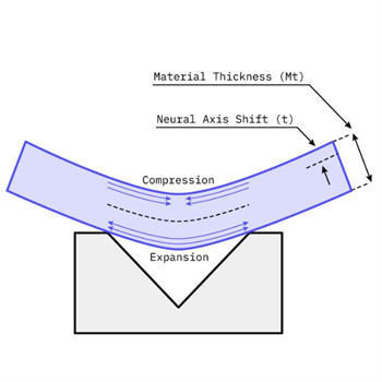
Creates flanges and three-dimensional shapes. Bend radius, flange height, tool access, springback and grain direction can affect the result.
Suitable when tooling investment is justified by quantity or when a formed geometry requires a dedicated process. Material flow and forming sequence need early review.
Used for cylinders, curved panels and continuous profiles. Radius, straight sections, seam location and quantity influence the selected method.
Drilling, tapping, countersinking and CNC machining can complete features that should not be produced by the primary cutting or forming operation.
One part may require several processes. For example, an enclosure can be laser cut, bent, fitted with threaded hardware, welded, ground and powder coated. Planning the complete sequence helps avoid inaccessible features, coating interference and unnecessary rework.
Do not select a process from geometry alone. Quantity, tooling cost, cosmetic standard, tolerances, material utilization and future repeat orders all affect the most practical route.
The following rules are useful starting points, not universal specifications. Final values depend on alloy, temper, thickness, tooling, bend method and the required part function.
A DFM review can identify bend collisions, insufficient tool access, distorted holes, weld-related movement, unsuitable tolerances and finishing conflicts before material is cut.
| Material Group | Typical Considerations | Common Applications |
|---|---|---|
| Aluminum | Low weight and corrosion resistance; alloy and temper influence bending, welding and anodizing. | Electronics housings, lightweight panels, energy and automation equipment |
| Stainless Steel | Corrosion resistance and strength; grade, surface direction, weld discoloration and passivation may matter. | Medical equipment, food equipment, outdoor enclosures and industrial assemblies |
| Carbon Steel | Cost-effective structural performance; usually requires a protective finish for corrosion control. | Frames, brackets, cabinets, machinery covers and welded structures |
| Galvanized Sheet | Protective zinc layer; cutting, welding and cosmetic expectations require process review. | HVAC, electrical cabinets and general industrial products |
| Copper & Brass | Electrical and thermal performance; temper, surface protection and joining method are important. | Busbars, contacts, shields and conductive components |
Color and corrosion protection for steel or aluminum parts. Define color, texture, gloss, masking and appearance class.
Common for aluminum. Alloy, surface preparation, color variation, contact points and dimensional build-up require review.
Zinc, nickel, passivation and other treatments are selected around material, corrosion target, conductivity and compliance needs.
PEM-type hardware, rivets, screws, studs and weld nuts can create serviceable or permanent joints. Hole size, sheet thickness and access direction must match the hardware.
Selected according to material, thickness, joint design, strength and cosmetic requirements. Fixtures and weld sequence help manage distortion.
Self-locating features can simplify assembly and welding, but clearances, bend sequence and coating build-up should be considered.
Laser cutting and CNC bending are often practical for prototypes and flexible production. When volume increases or the component needs repeated formed features, progressive, compound, transfer or deep-draw tooling may reduce cycle time and improve consistency.
Tooling investment, projected volume, material utilization, secondary operations and expected die life should be evaluated together.
Send drawings, CAD files or sample photos to info@hms1688.com. Our team can review the material, cutting and forming route, assembly method, finish and production quantity before quotation.
Request Sheet Metal Project ReviewCustomer drawings, models and manufacturing information are handled confidentially. NDA support is available for custom projects.
Prev: Cutting Service

Contact us and just send us your drawing (SolidWorks,ProE,CAD,PDF,DXF...)
Links: Custom Sheet Metal Enclosure Fabrication | Metal Stamping Services | Sheet Metal Fabrication Services | precision cnc machining and milling services | Metal Welding Services | metal Cutting Services | Metal Bending Service | Metal Surface Treatment & Finishing Solutions |